|
|
In this section, we will build a ReqIF model from scratch, step by step.
The easiest way for installing ProR is downloading formalmind Studio. This is a standalone-application that is based on Eclipse ProR, combined with some enhancements.
Alternatively, you can install ProR in any Eclipse-Installation via its update site (listed on the RMF Download page). This is recommended for advanced users only who need to integrate RMF with other Eclipse-based components.
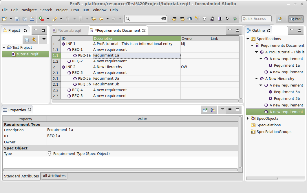
After this, your window should look more or less as shown in Figure 3.1.
You will see your ReqIF file in the Project Explorer window (1).
The Specification Editor (2) shows your Specifications.
In the Specification Editor, you see the SpecObjects that exist in this Specification. There is currently only one, with the description “Start editing here”.
The Outline (3) has four folders:
The properties of a selected SpecElement are shown in the Properties View (4). As the only SpecObject in the model is selected, we see its SpecType (“Requirements Type”) and its only Attribute (“Description”) with the value “Start editing here.” There are two tabs Standard Attributes and All Attributes at the bottom of the Properties View. The Standard Attributes tab shows you all standard attributes of the selected element. All Attributes shows all existing ReqIF attributes of the selected element.
Above the main working windows it the tool bar (5) and, at the very top, the menu bar (6).
To get familiar with the tool, we will:
The results of this are shown in Figure 3.2.
To add new attributes, we open the Datatype Configuration dialog with ProR
| Datatype Configuration. Alternatively you can also click on ![]() in the Tool
Bar.
in the Tool
Bar.
The resulting dialog box has two folders in the upper pane: one for SpecTypes and one for Datatypes. Currently, there is only one Datatype “T_String32k” and two SpecTypes, one called “Requirements Type” with the attribute “Description” and one called “Specification Type” with the attribute “Description”.
In the lower pane are the details in regards to each attribute.
We add more Attributes to “Requirements Type” by right-clicking it and selecting New Child | Attribute Definition String. This will create a new element. Upon selecting it, we can rename it and tailor the details. Double-click on the “Long Name” variable and type in “ID”. Change the Type by double-clicking the field and choosing “T_String32k” from the dropdown menu. Repeat the process but this time change the “Long Name” to “Owner”. In the end, the dialog should look as shown in Figure 3.2.
Upon closing the dialog, little will have changed - the Specification still shows just two columns, Description and Link. However, if you select the requirement, you will see the new Properties (ID and Owner) in the Property view.
To show the new Attributes in the Specification, we have to configure the columns
shown in the Specification Editor. We do this by selecting ProR | Column
Configuration. You can also click on ![]() in the Tool Bar.
in the Tool Bar.
The resulting Dialog shows one entry, “Description” for the one and only Column of the Specification. In the “Value” column double click on “Description to choose it and replace it with “ID”.
By clicking on the “Add Column” icon at the top of the dialog, create a new column and name it “Description”. In this view, the columns can be dragged and dropped to change their order as desired.
The resulting window is shown in Figure 3.3.
You can actually adjust the width of the columns simply by dragging the column headers.
Now we can finally add SpecObjects by right-clicking on a row in the Specification View. In the context-menu, there are two submenus: New Child and New Sibling.
In both menus, there are three entries Spec Hierarchy, SpecObject and SpecObject (Requirement Type). Some background is needed here:
We said before that Specifications contain references to SpecObjects. A SpecHierarchy is the wrapper that allows the hierarchical structure and that points to the referenced SpecObject. Usually, we don’t have to be concerned with them. Therefore the second option: If selected, a new SpecHierarchy is created and associated with a new SpecObject, which in turn is set immediately to the given SpecType. If we had more than just one SpecType (besides “Requirements Type”), there would be an entry for each SpecType in the context menu.
To continue the exercise, select the New Child | SpecObject (Requirement Type). Now we have two SpecObjects. The original is numbered on the far left-hand side of the pane with a “1”. The second one, the child, is numbered “1.1”. Now we should change the ID’s of each entry. Click in the cell of the column “ID“ (in row 1) and type in INF-1. Under Description, type ”A ProR tutorial.“ For the second, change the ID to REQ-1 and ”Learn how to create a new requirement” in the “Description” column.
Feel free to add a few more rows and or even new structures. Yours should look somethinig similar to Figure 3.4.
SpecObjects can be reordered by using drag and drop. This works both in the Specification View and the Outline View.
You can drag and drop a SpecObject as a sibling or a child. The highlighting feedback will enable you to see what you’re moving and where to. For instance, if you are dragging a SpecObject over another one, the entire cell will be highlighted. This means, that the SpecObject will be assigned as a child to the dropped SpecObject.
If you are dragging a SpecObject between two rows, you also get visual feedback on whether the SpecObject will be assigned as a sibling.
Figure 3.5 shows drag and drop in action.
You can also move elements by using cut and paste. Pasting will insert an element as a child.
If you want to export your Specification as HTML, open the Specification you would like to export and initiate printing File | Print.... The HTML representation is generated and opened in your system’s web browser.
Quite an achievement—but there’s still a bit of a way to go. One improvement we can make is simplifying data entry. Another is improving the visibility of the descriptions. In the next part of the tutorial, we will address these issues.